

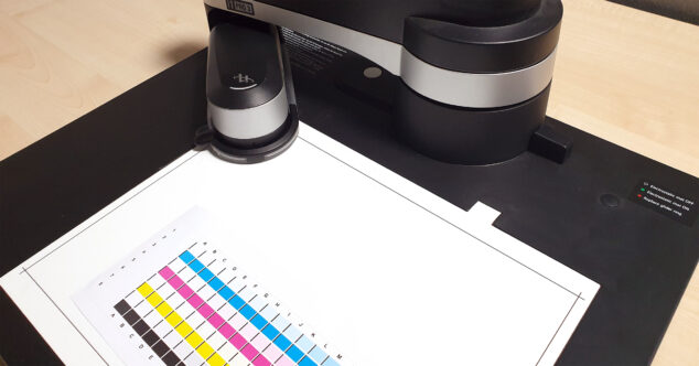
In the last couple of weeks there have been more reports about issues with measuring linearization or profiling charts with the X-Rite i1Pro 3 or i1Pro 3 Plus and the iO3 measuring table. However, with the following tips, they can usually be fixed.
Symptoms may include:
- The i1Pro 3 gets stuck on paper edges. Possible cause: No glider ring inserted into the slider of the iO arm.
- Some rows are measured correctly, then the device stops or performs uncoordinated movements and drives back to its parking position. Possible causes:
- No glider ring or glider ring with wrong aperture size was used
- The iO arm was not locked correctly on the iO measuring table
- The i1Pro 3 was not inserted correctly into the slider of the iO arm
- During the preparation of the test chart measurement, the positioning aid was not set in the middle of any of the three anchor points (color patches top left, bottom left and bottom right).
- The iO / i1Pro 3 measures the test chart but falls back from fastest measurement speed to a slower speed and further to single measurement mode, or some extreme mismeasurements occur. Possible causes:
- No glider ring or glider ring with wrong aperture size was used
- The iO arm was not locked correctly on the iO measuring table
- The i1Pro 3 was not inserted correctly into the slider of the iO arm
- The height of the iO arm is not optimally adjusted to the thickness of the substrate
- The layout (color patch size, total size, color patch separators) of the printed test chart is not optimal for the used substrate or printing technology
However, the following tips do usually help to fix these issues:
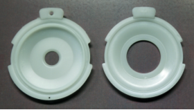
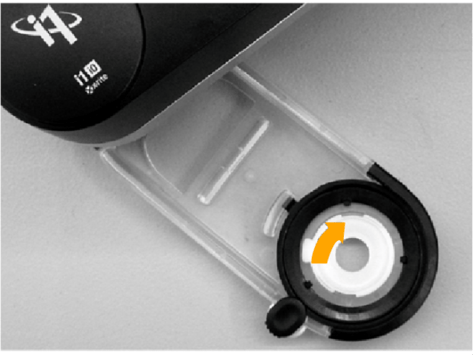
- Make sure the correct glider ring has been inserted into the slider of the iO arm. Other than with the iO of first or second generation, the iO 3 is delivered without a pre-assembled glider ring. This is due to the fact that the new i1Pro 3 is delivered in two variants with different measurement aperture sizes (4.5 or 8 mm), which can both be used with the iO 3. For this purpose, two glider rings – one for the 4.5 mm, one for the 8 mm aperture – are included in the box of the iO3. Depending on which device you are using, the glider ring which matches to the aperture of your i1Pro 3 must be used. If this is forgotten, the i1Pro 3 does not slide evenly over the test chart and fails to overcome the material edges. Due to the friction of the device on the substrate, the movement of the slider can also get stuck, which can lead to a break of the measurement or faulty measurement data. If the correct glider ring is mounted, this problem is solved.
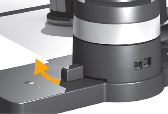
- Please also check that the iO arm is correctly mounted on the iO table and that the lever for fixing the arm is closed until the stop. This is essential for a precise positioning of the iO arm and an exact scanning of the test chart to archive accurate measurement data.
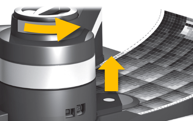
- Check the height adjustment of the iO slide to the substrate. The height is usually set to the thickness of the substrate to be measured. The aim is that the slider with the i1Pro 3 moves plan and without bending over the entire measuring surface also to the outer areas. Rotate the height adjustment screw until the white reference plate touches the substrate (for substrates up to 1mm thickness no height adjustment upwards is necessary, leave the arm in the lowest position).
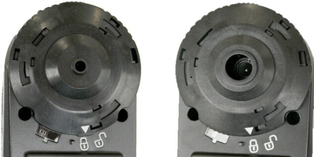
- Make sure the i1Pro 3 is inserted correctly into the slider of the iO arm. The measuring hole of the
i1Pro 3 must be fully locked into the measuring hole of the glider ring in the slider. The black slider must be fully open so that the positioning aid (crosshair) becomes freely visible. This ‘approves’ that the i1Pro 3 is correctly locked in the slider.
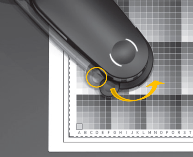
- When setting up the test chart measurement, make sure that the test chart is cut along the dotted lines, that it does not cover the black boundary lines on the iO table! This helps you to place large test charts correctly in the inner measuring area. Also, when setting up the measurement, make sure that the positioning aid on the slider is targeted as precisely as possible to the middle of each of the three anchor points (color patches top left, bottom left and bottom right). For test charts with very large, possibly not square color patches, it is recommended to take a closer look to the positioning of the crosshair on the color patch from all sides, so that it is positioned in the middle. Based on the set anchor points, the dimensions of the test chart are calculated (color rows, color patches count and size). Errors in setting anchor points could lead to growing errors during scanning the color patches, and thus to color patch detection errors.
- If all above mechanical settings are executed correctly, but measurements on difficult substrates are still wrong, or if scanning speed still falls back from fast mode to single measurement mode*, an adjustment of the testchart layout (color patch size, total size, color patch separators) can help to solve this.
The following phenomenon is related to the mass of the i1 Pro3: Depending on the angle between the slider and its direction of movement, it can happen that the i1Pro 3 deviates somewhat from its intended scanning direction by overshooting. This movement is recognized and corrected by the iO. This leads to a characteristic “wobbling” of the i1Pro 3 during gliding across the test chart. It happens that measuring fields are missed and incorrect values are sent to the software. The lower the friction between the glider ring and the substrate to be measured, the more likely the phenomenon could occur.
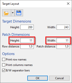
A solution is simple: By default, the ColorGATE Productionserver is using the smallest possible color patches to the maximum possible number of color patches to the available measuring area on the iO table. To improve the measurement stability, select larger patches in width and height in the ‘Target-Layout’ setting in the Linearization or Profiling wizards. Often the larger patches do even speed up the measurement process.
For structured substrates with high friction, it may also be advisable not to use the maximum measuring surface (32 x 23 cm) of the iO table to avoid having to drive the iO arm to the maximum outside areas (here the exact positioning becomes more difficult).
For substrates/prints with very low resolution, strong structures or very small color gamut, the use of separators (black, white, contrasting separators) between the color patches can stabilize the color patch recognition in addition to larger color patches in the scanning direction.
*Note: Throttling the scanning speed from fast to slow scan mode or further to single patch measurement mode is not a mechanical problem of the iO table, but is done automatically, if for the above reasons the color patch detection does not work in fast scan mode. This is to ensure that a measurement of the test chart can also be completed on critical materials.
0 Likes